February 2004
Article by Mike Whaley
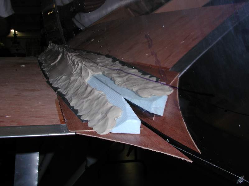
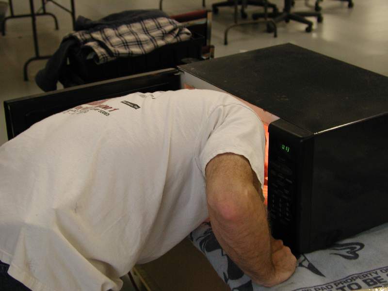
February saw us continuing with the construction of the fuselage skin panels and the creation of fiberglass wing-root fairings. These were built by attaching the lower wings and making a very rough sub-frame to support the fillet using blue foam and scrap plywood. The wooden sheeting in the wing root area was first covered with a layer of duct tape in order to protect it, then modeling clay (many pounds of it) was applied to shape the fillet. The clay is much easier to work after microwaving… about 3 minutes on “high” seemed about right for a hand-sized block of clay.
After applying clay and rough sculpting, we formed the right shape… a bit longer and it was all smoothed out. When it was “just right”, we applied layers of fiberglass cloth over the clay to build up the prototype wing fairing and subsequent mold form. This not only covers the wing root area, but extends forward as well to fair in the area where the landing gear leg meets the fuselage.
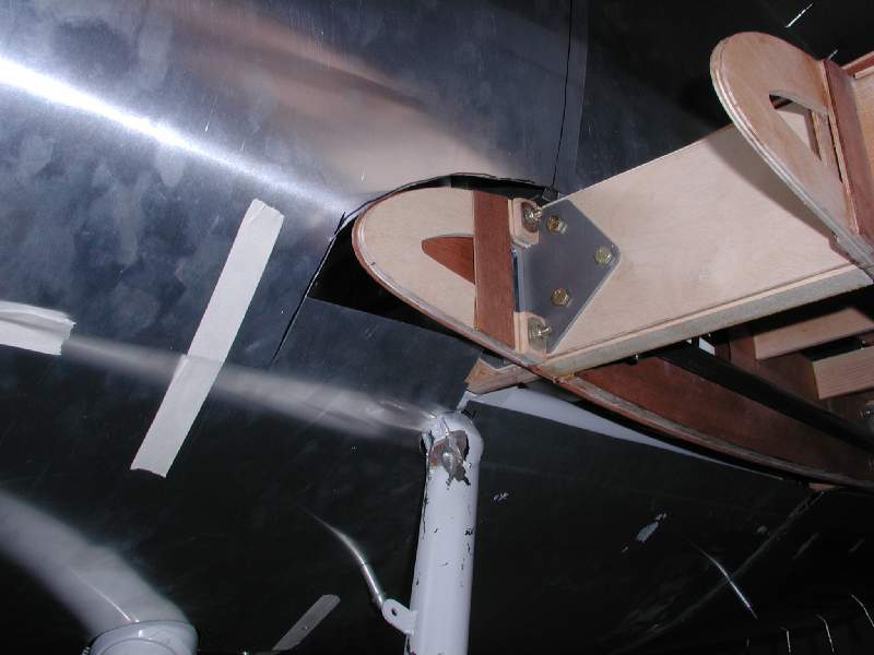
After the epoxy cured, we removed the fiberglass, cleaned up the edges, sanded it a bit, and were pleased with the results. The fairing is attached to the fuselage via quick-release fasteners, which are anchored to the aluminum side formers. We then carefully trimmed the hinged aluminum side panels to overlap the fairings over an aluminum angle stiffener.
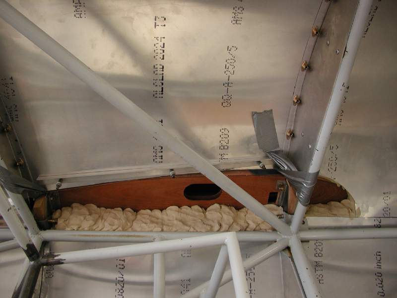
On the inside of the cockpit, we installed small aluminum panels to cover the wing root area. It will be easy to get into this area when needed for inspection, but most of the time you won’t want or need to see it.
The lower edges of the side panels anchor to the fiberglass fillet using camlocks, while the edges of the panels anchor to the aluminum fuselage formers using the same type of fittings. The fiberglass and interior pieces also anchor to the formers in the same way. In most areas, there is a sandwich with the side panel and faring being held with a common connector.
In the end, we have achieved the goal of easy maintenance access, ease of construction, and low weight, while also making for a neat and attractive installation.
The design allows the panels and fairings to be factory supplied with final trim on two sides done at installation. The sheet metal is one of the more labor intensive areas of construction, and we aim to greatly reduce this effort for builders.
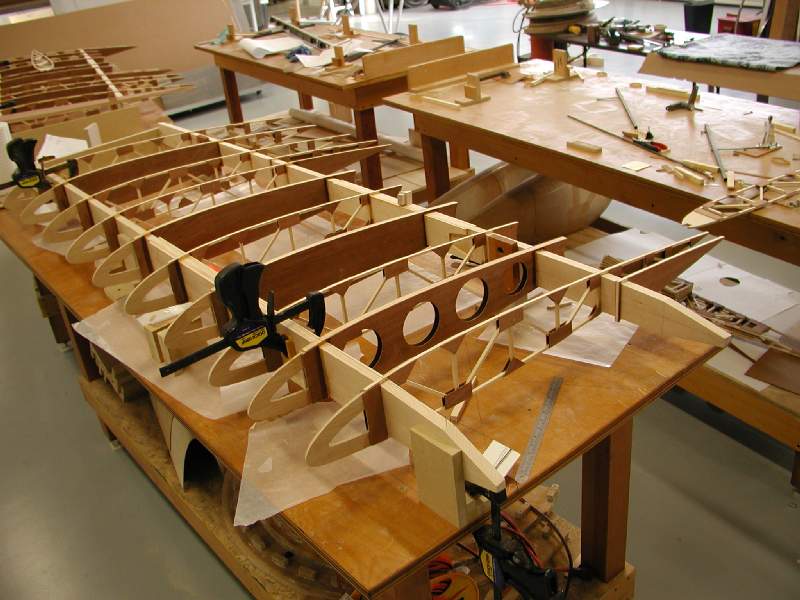
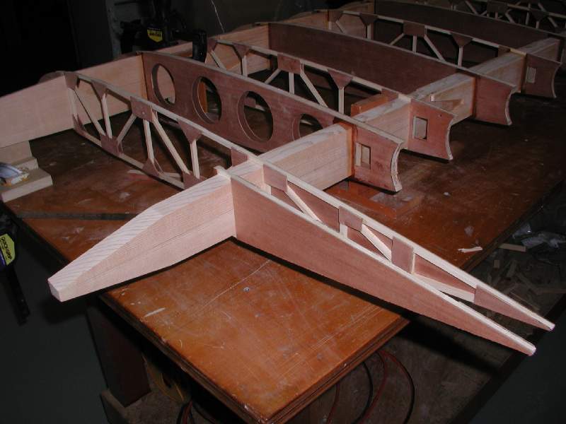
In February we also began the process of building the upper wings. These are nearly identical to the lower wings; they differ in hardware and a few details. We have also been working on the layout of the upper wing center section, building a quick mockup with pine spars to ensure that the wing fuel tank and fittings all work out as expected.
As this is written (mid March) we’re only a month away from Sun N Fun 2004. We will have the Model 14 prototype there, of course.
We are trying to make as much progress as possible, though the days before SNF are hectic to say the least. We pack up all sorts of displays, our tents, and get set up so that most of the company plus family members can camp comfortably in Lakeland for a week and a half… no small undertaking.
As we’re fond of telling people, the prototype will be done on Tuesday – we leave the question of which Tuesday a bit open to speculation.
-

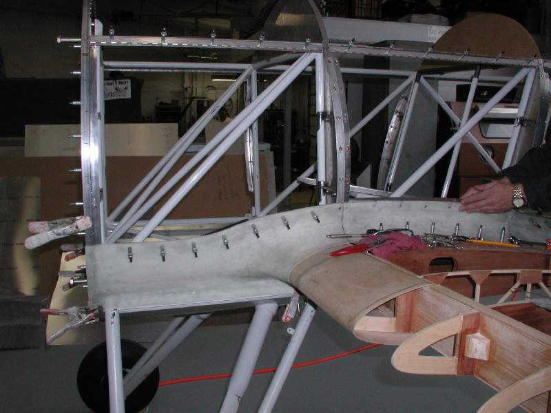
- Prior to making the wing fairings, the side panels were rough trimmed to clear the wing root to enable the panels to close.
-
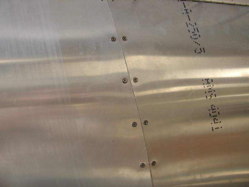
- Each panel is fastened down separately using flush quarter-turn fasteners.
-
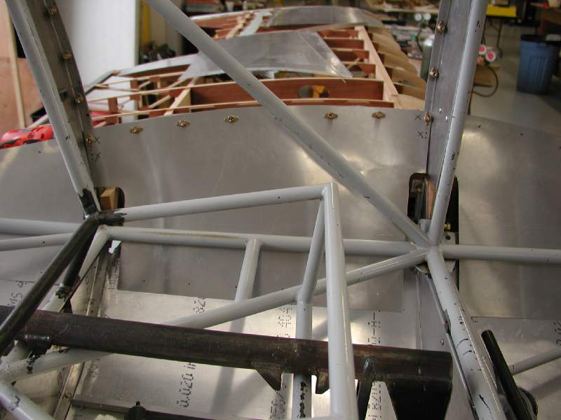
- Blue foam and scrap wood was used to provide a solid support base for the clay.
-
- Here you can see the thin plywood frame that gave the clay a solid base foundation. The wood was simply secured with duct tape to the aluminum skin.
-
- Barrett Brummett (left) and Paul Goetsch apply the first layers of modeling clay.

-
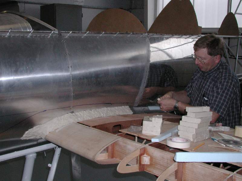
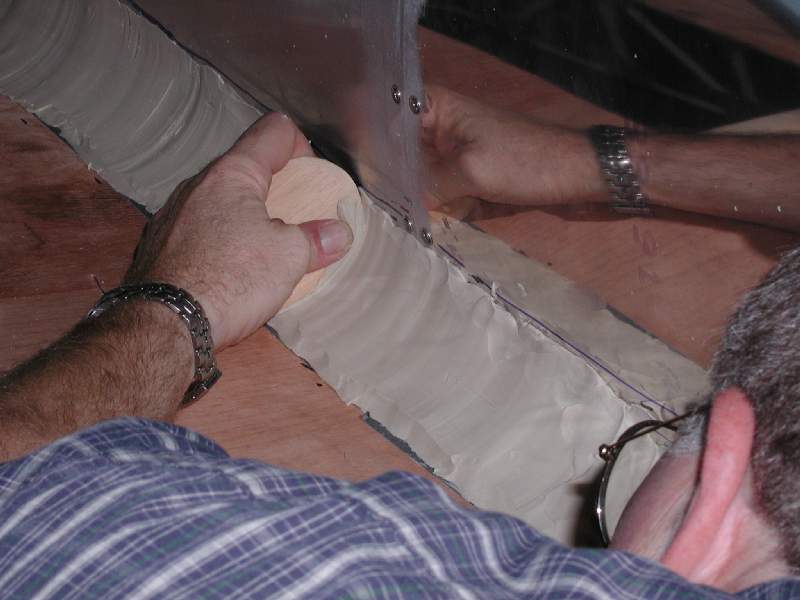
- Steen president Paul Goetsch applies clay to the wing root area. Each block of clay was heated in the microwave for about 3 minutes to soften it.
-
- The clay mold is beginning to take shape.
-
- Preliminary smoothing of the clay.
-
- You can use any handy object to help you shape the clay.
-
- The clay is sculpted to create a smooth fairing over both the wing root and the landing gear/fuselage junction.
-
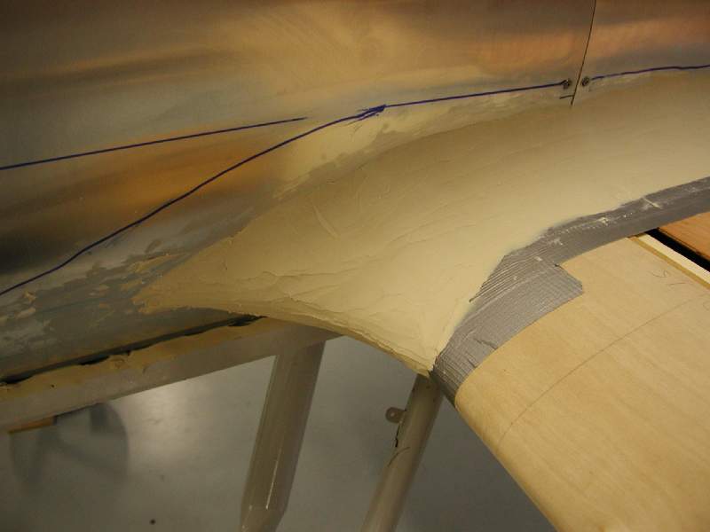
- The clay has been shaped and smoothed in preparation for covering it with fiberglass. The fiberglass will provide the farings for the protorype, and will be used to “take-off” the final production molds.
-
- Barrett performs an annual inspection on the microwave.
-
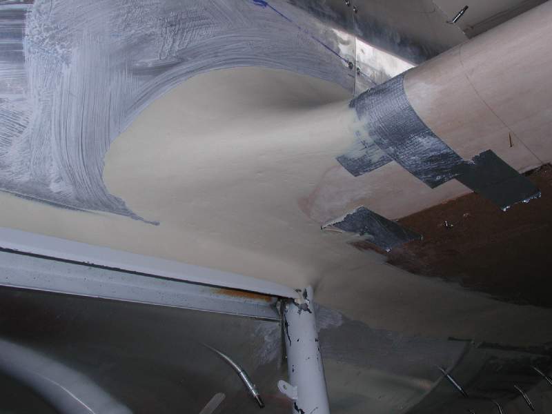
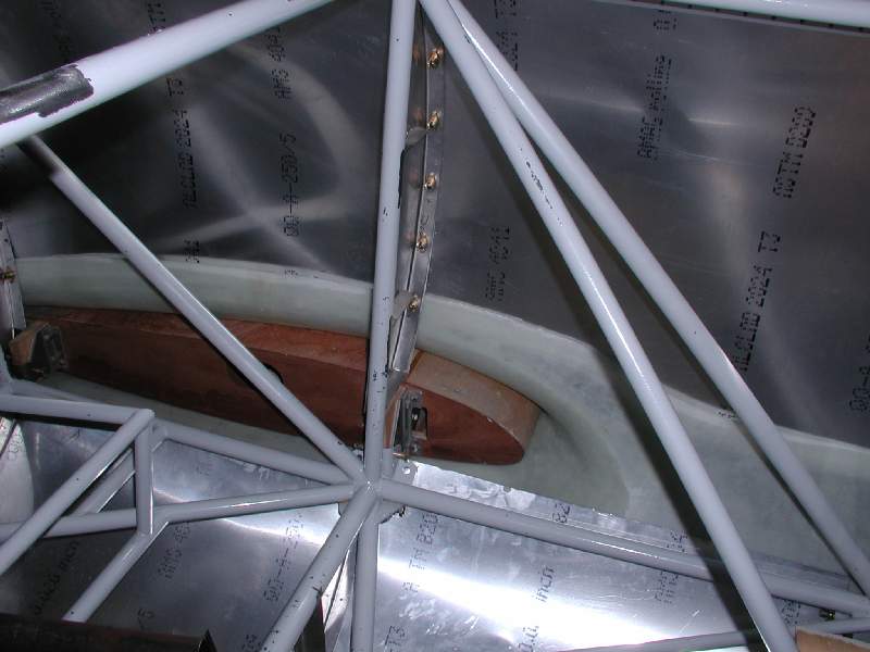
- The clay sticks to the underside just fine, as long as the supporting framework is secure.
-
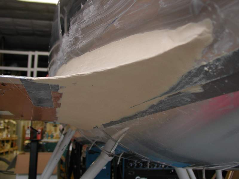
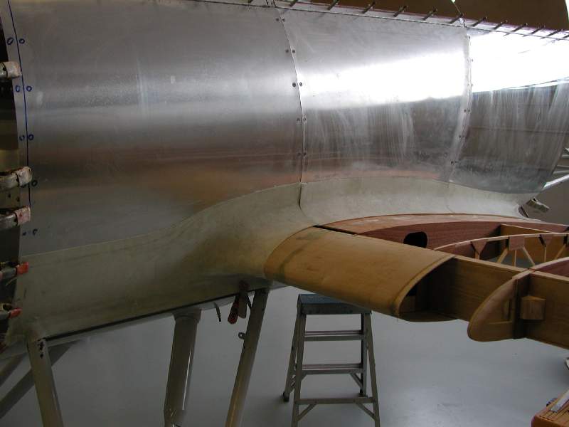
- The landing gear leg / fuselage junction is also faired in an integrated system.
-
- The rear of the mold, before final surfacing.
-
- The trailing edge section ready for glass.
-
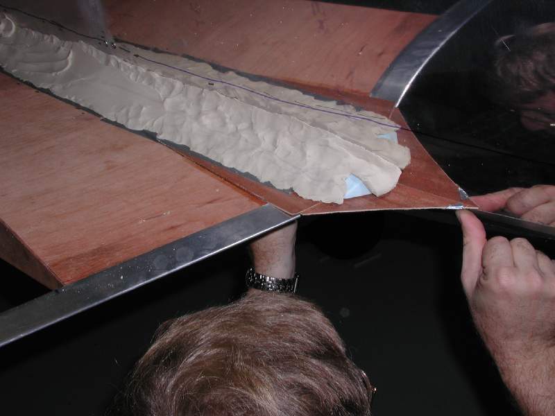
- The clay completely fills the gap between the wing and fuselage skin.
-
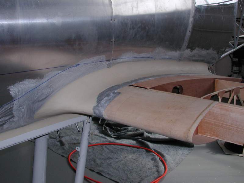
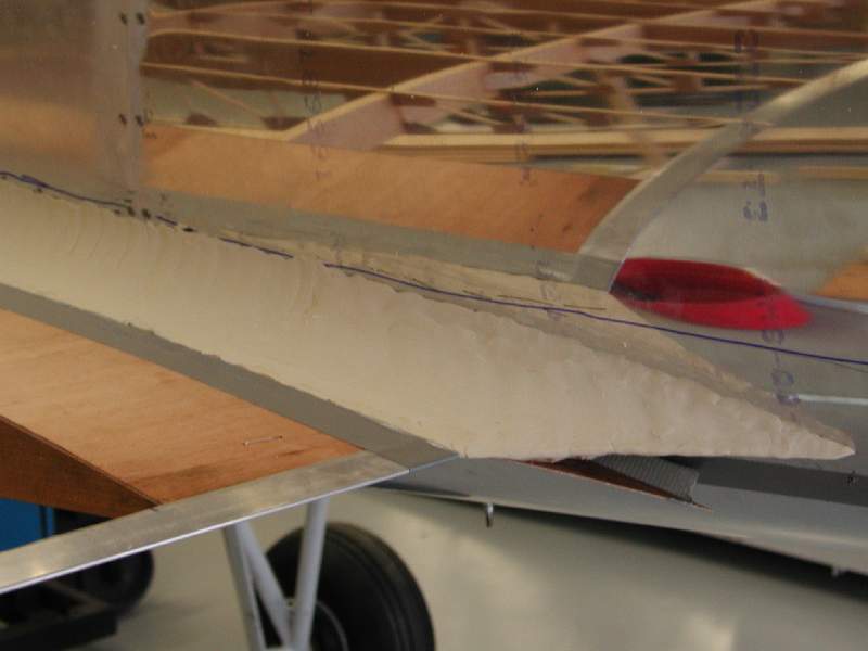
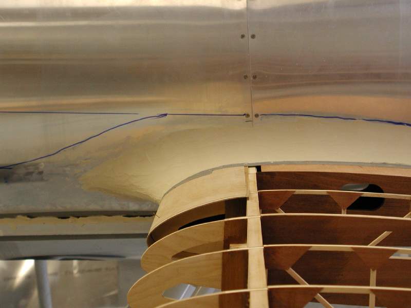
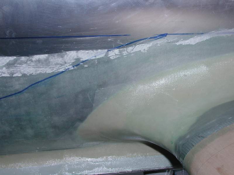
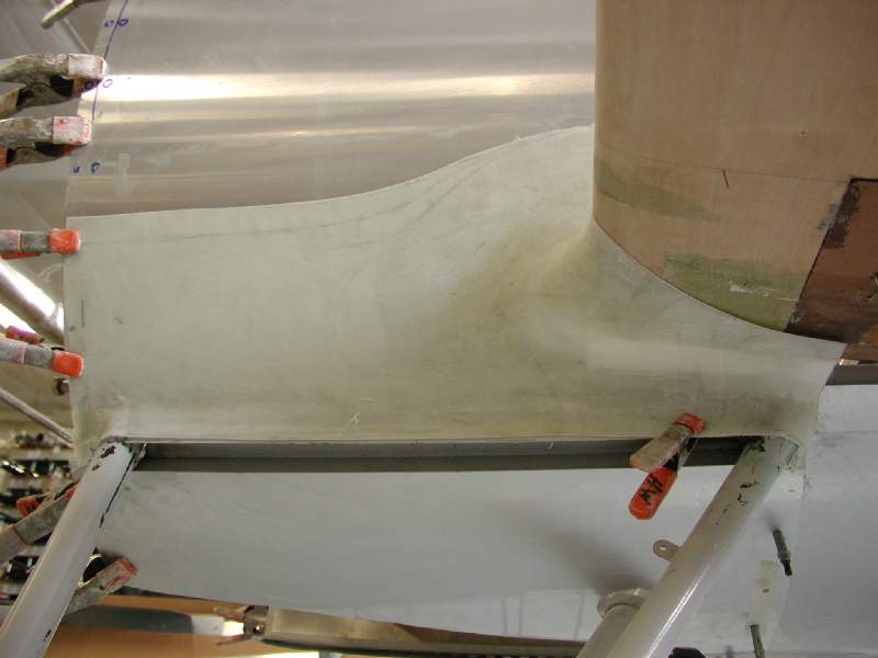
- The blue line marks the planned edge of the exposed fiberglass. It must overlap this line in order to allow room to underlap the side panels and fasteners.
-
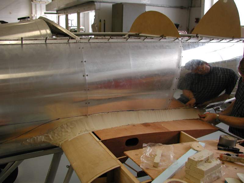
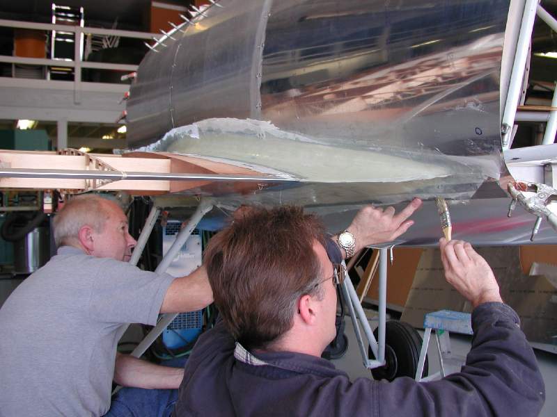
- John Hollister (left) and Barrett Brummet apply fiberglass cloth.
-
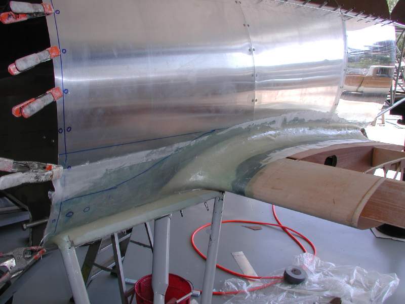
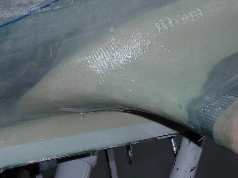
- The first layer of fiberglass cloth has been applied and brushed down.
-
- The fiberglass is built up in layers, with care taken to avoid air bubbles.
-
- Several layers of fiberglass cloth are applied.
-
- The fuselage/landing gear junction is also covered with a fairing.

-
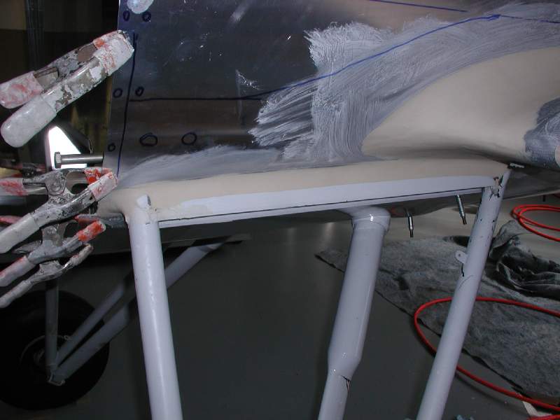
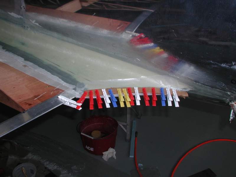
- The rear edge is clamped to ensure that the top and bottom layers of fiberglass are firmly joined together.
-
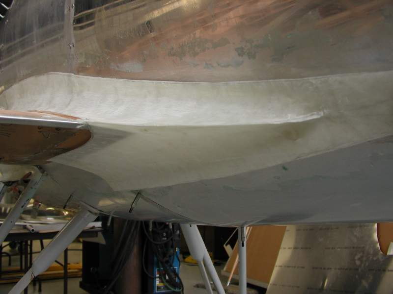
- There is still a bit more finishing needed, but the basic shape has been created.
-
- The fairing has been trimmed and separated into sections.
-
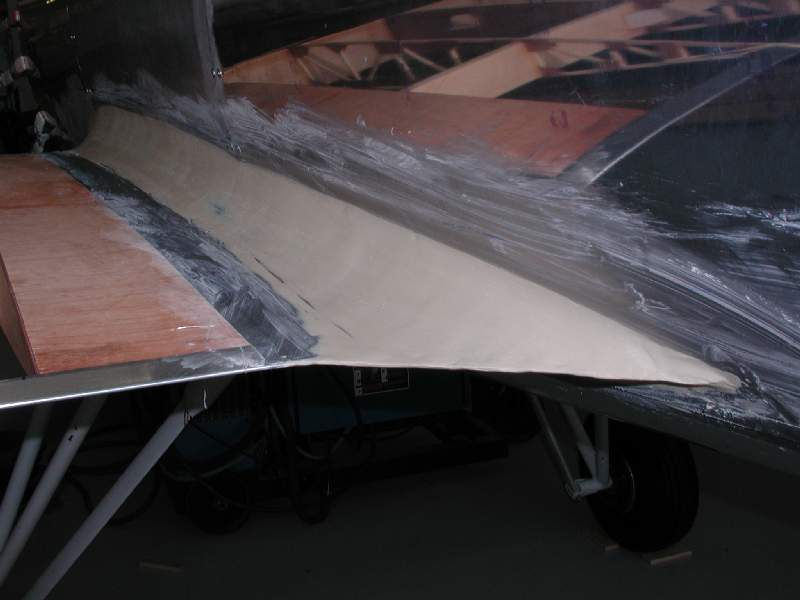
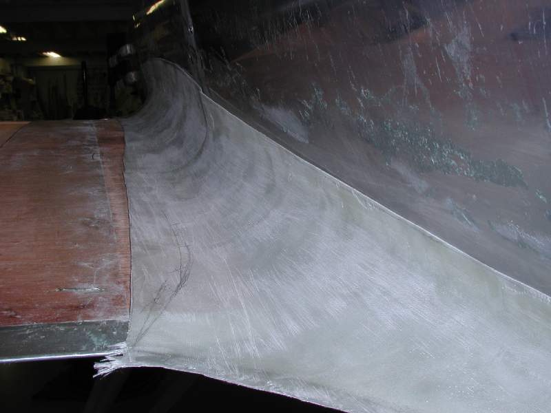
- This will provide an elegant, smooth transition from the gear leg into the wing-root faring.
-
- Here you can see the front section of the fairing.

-
- The trailing edge fairing really gives an elegant shape.
-
- This is the wing root area beside the rear seat. The fairing is installed, but it hasn’t yet had the fasteners installed to attach it to the lower edge of the side panel.
-
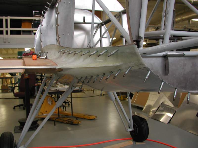
- The side panels are trimmed to overlap the outside of the fiberglass fairing.
-
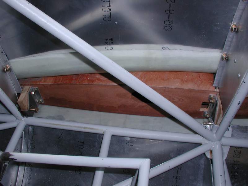
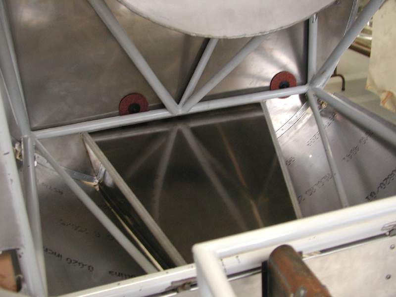
- Here you can see the interior panels which close-out the wing root from the inside of the cockpit.
-
- Here we are fitting the interior panels to the inside of the fairing.
-
- Clecos hold the interior panels to the fairing while the fasteners are installed.
-
- Here you can see the large channel for coolant air exit.
-
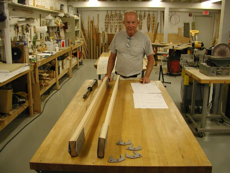
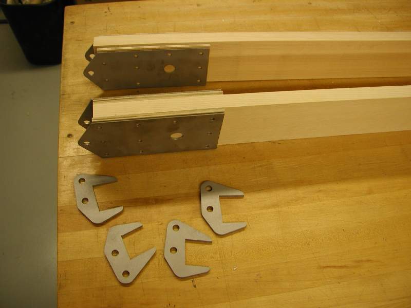
- John Hollister shows us the upper-wing center-section spar assemblies.
-
- Some of the attach fittings that join the upper wing’s outer panels to the center section.
-
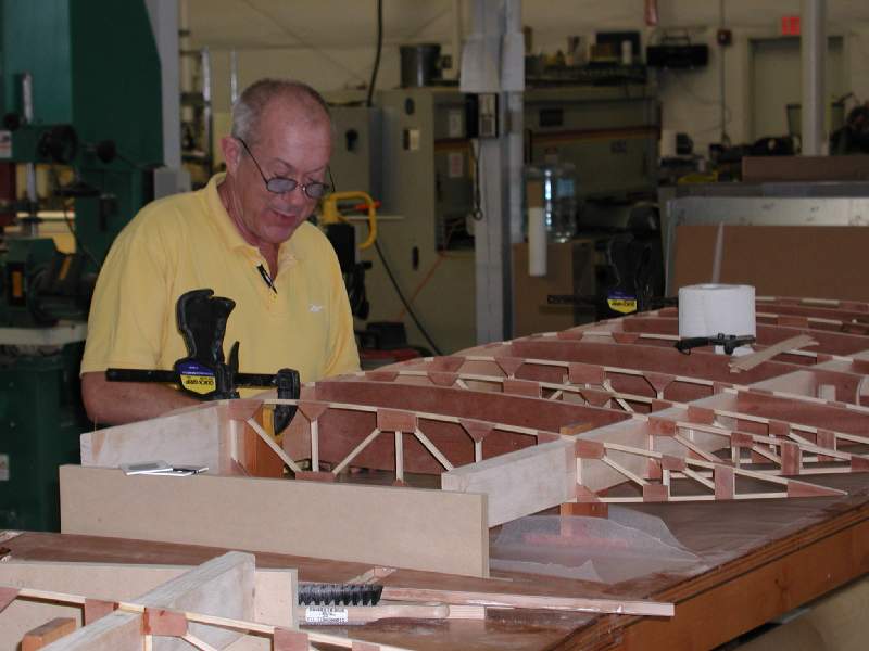
- John locates ribs during construction of the upper wing panels.
-
- The upper wing panels are nearly identical to the lower. This alows all four wings to be built on ONE short wing table if necessary.
-
- Not all of the ribs are glued in yet, pending final checks.