January 2004
Article by Mike Whaley
We are happy with the fuselage skin design. It has been a lot of work to get it right, but the benefit to our builders will be great. The side panels are aluminum and are piano-hinged along the top longeron and are secured along the sides and bottom with camlocks. There are three panels on each side (four including the cowling panels forward of the firewall), and each may be opened independently. This allows maximum maintenance access to all internal systems.
The bottom fuselage panels are also easily removable with fasteners in the conventional manner, since most inspection and maintenance tasks can be accomplished through the side panels. The section of the fuselage aft of the rear cockpit will be covered in fabric, with removable inspection plates installed as necessary.
Part of the fuselage panel design incorporates a fiberglass wing-root faring between the fuselage, the lower wing, and the landing gear leg.
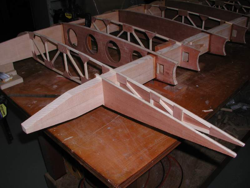
As we wrapped up construction details on the lower wings, including shaping the foam wingtips and installing control linkages, we have begun primary construction of the upper wing panels. They are nearly identical to the lower wings, and differ only in the details.
-

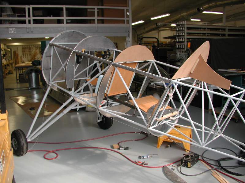
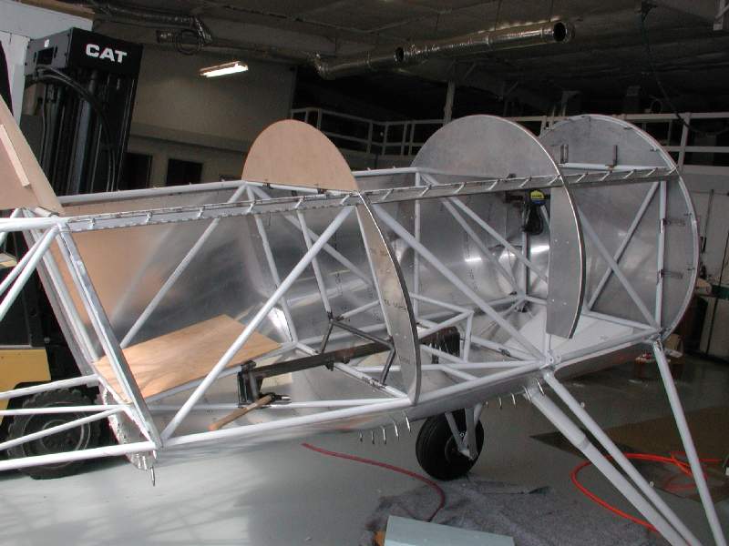
- The fuse formers have been completed. The rear seat headrest and support are dummy templates to establish the shape of the turtledeck.
-
- If you look closely, you can see the piano-type hinges installed along the upper longeron. These panels will provide quick and complete access to the entire interior!
-
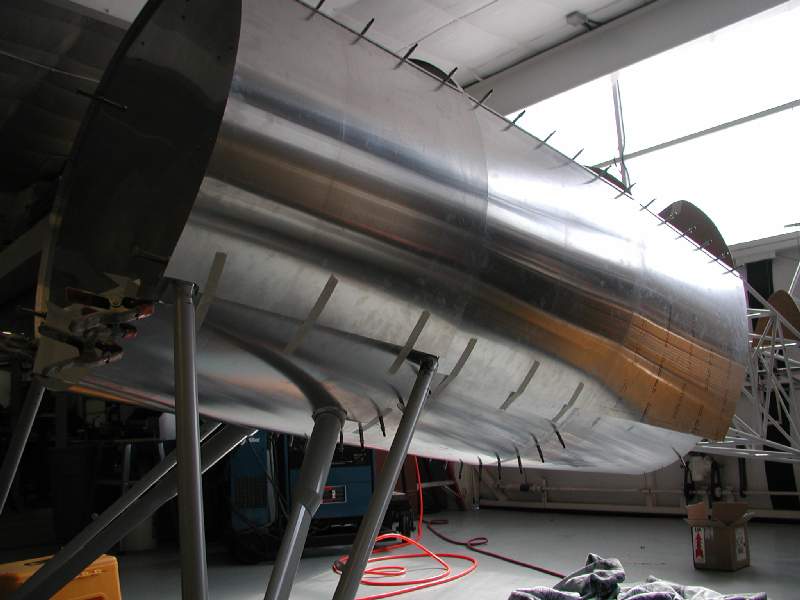
- The fuse takes shape, this time in the final metal. The panel transitions are smooth, natural, and elegant. Cudos to Barrett. He is a innovative builder with deep experience.

-
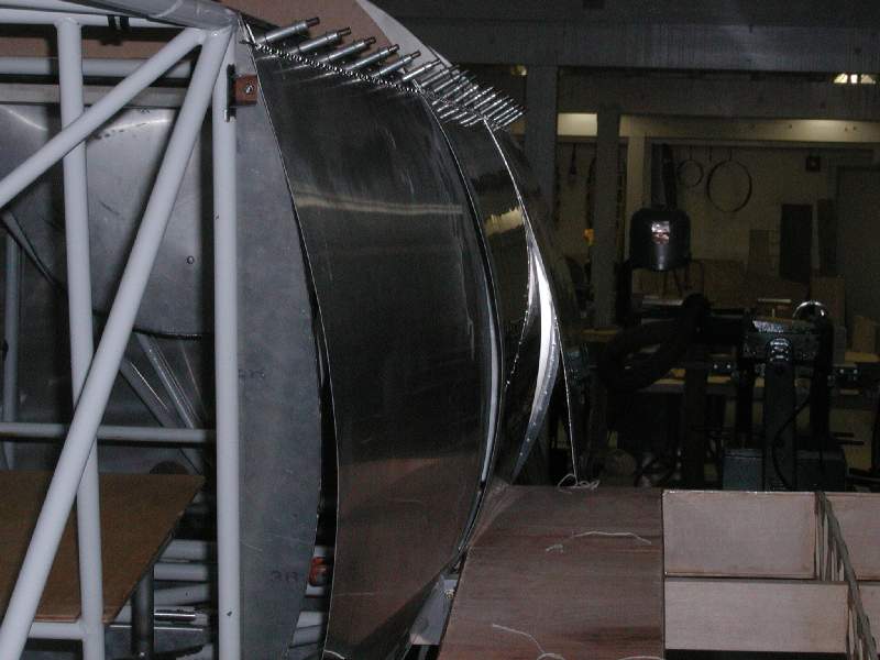
- Preliminary fitting of the prototype panels with clecos. Subsequently, the bottom edges were trimmed to overlap the wing root faring.
-
- The cowling air exhaust will exit through this deep channel in the bottom of the fuselage skin.
-
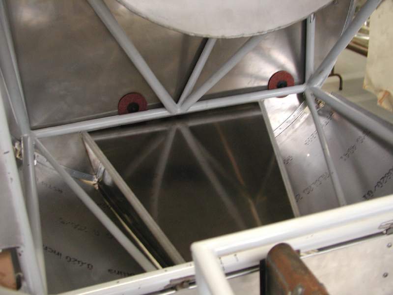
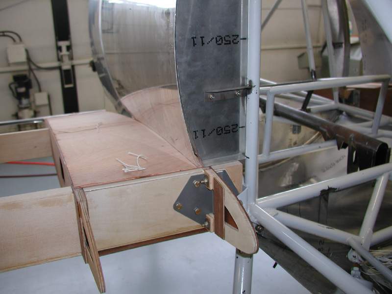
- The formers are fastened to angle brackets which are welded onto the airframe. This station is actually the firewall, which is also attached at the four engine mounting spools.
-
- This shot shows how the side panels will allow you to inspect and maintain interior components of the cockpit.

-
- The panels are secured with camlock fasteners. You will not need to open one panel in order to be able to open the next one, as they do not overlap.
-
- Here, the panels are being rough trimmed to clear the wing. They will be trimmed further to overlap the fiberglas wing-root farings between the fuselage and wing.
-
- Another view of the panel initial rough trim around the wing.
-
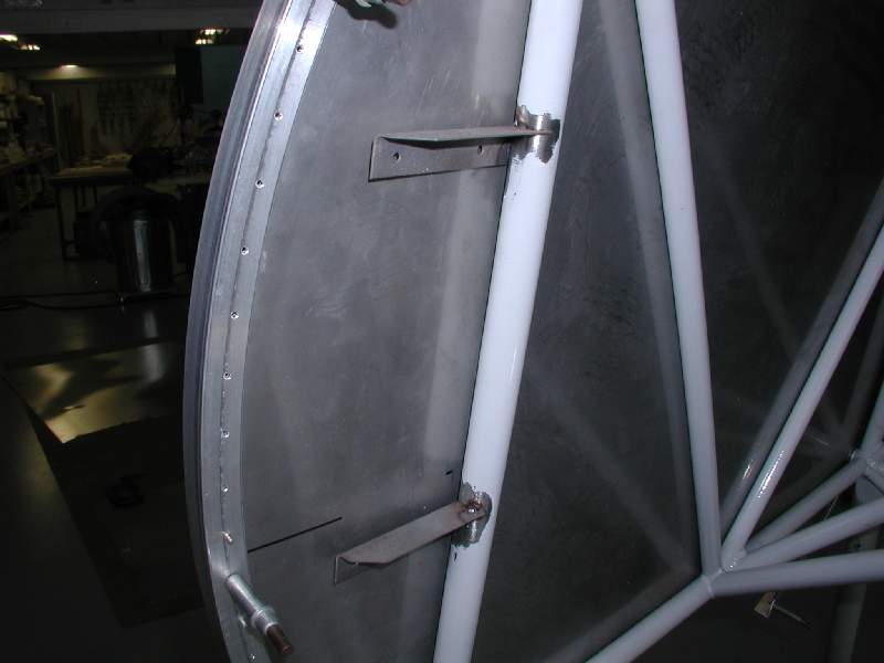
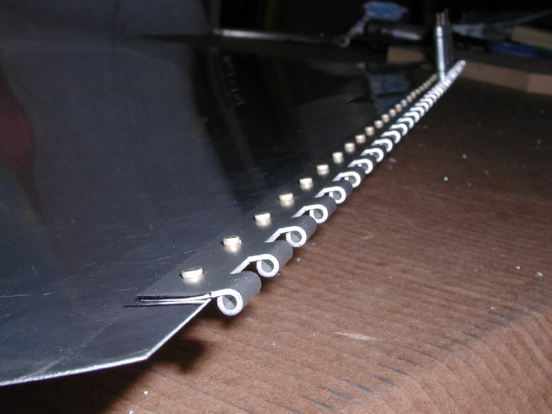
- These are rolled aluminum hinges attached to the upper edge of a side panel with rivets. Extruded piano hinges, often used on flight control surfaces, are stronger (since they’re molded as one piece and thus don’t have the gap in the loop) but they cost a great deal more. For this particular application, rolled hinges are the right choice.
-
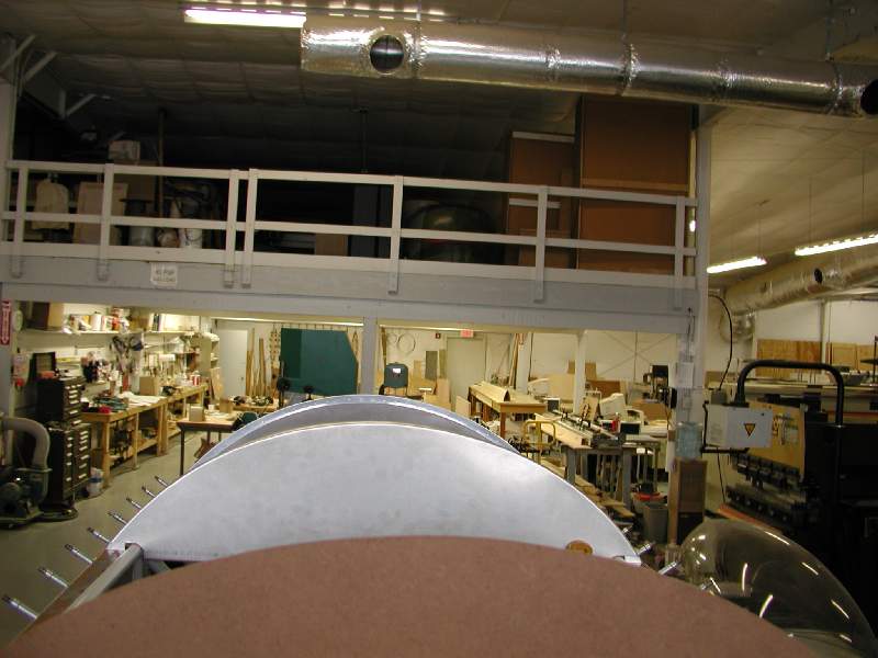
- This photo was taken with the camera placed where the pilot’s head will be. The visibility with the fuselage will be good. Taxiing visibility will be typical of radial engine biplanes.
-
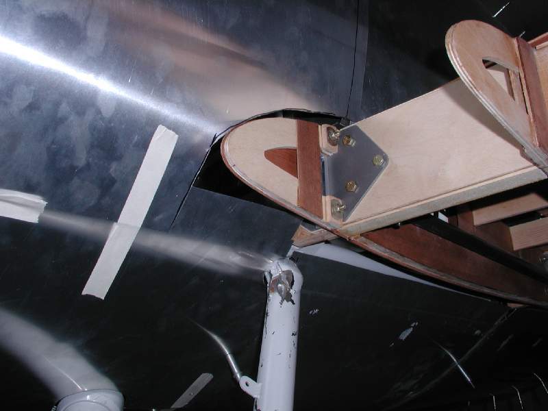
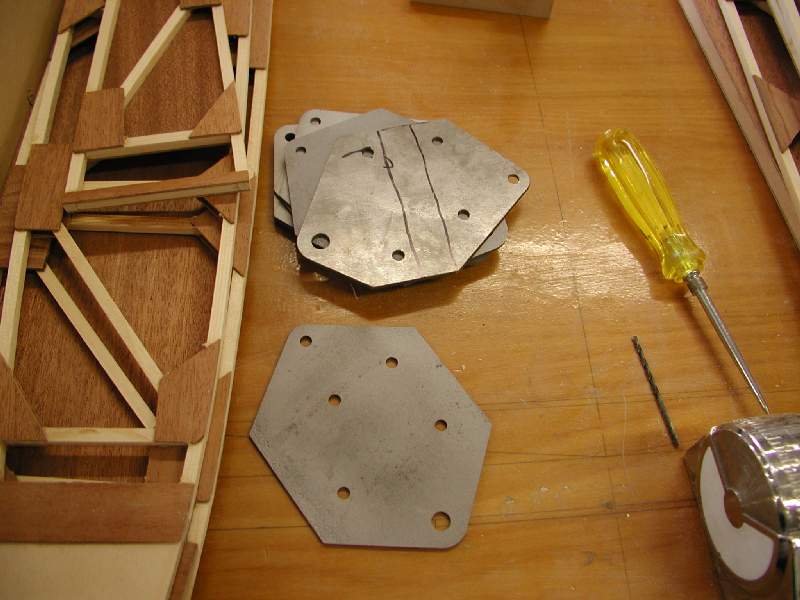
- These are the 4130 wing-attach plates which thru-bolt onto either side of the butts of the upper wing spars where they attach to the center wing section.
-
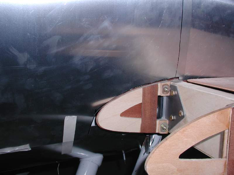
- The lower wing has been fitted and rigged to the proper dihedral in preparation for shaping the mold pattern of the fiberglass wing-root faring.
-
- Foam is glued and formed to the wingtip profile. The prototype will be used to extract mold forms for fiberglas wingtips to be used on customer aircraft. The wingtip shape will be enforced using a special expanding foam. On the prototype, the foam will be covered with light fiberglass cloth for skin strength and dent resistance under the fabric.
-
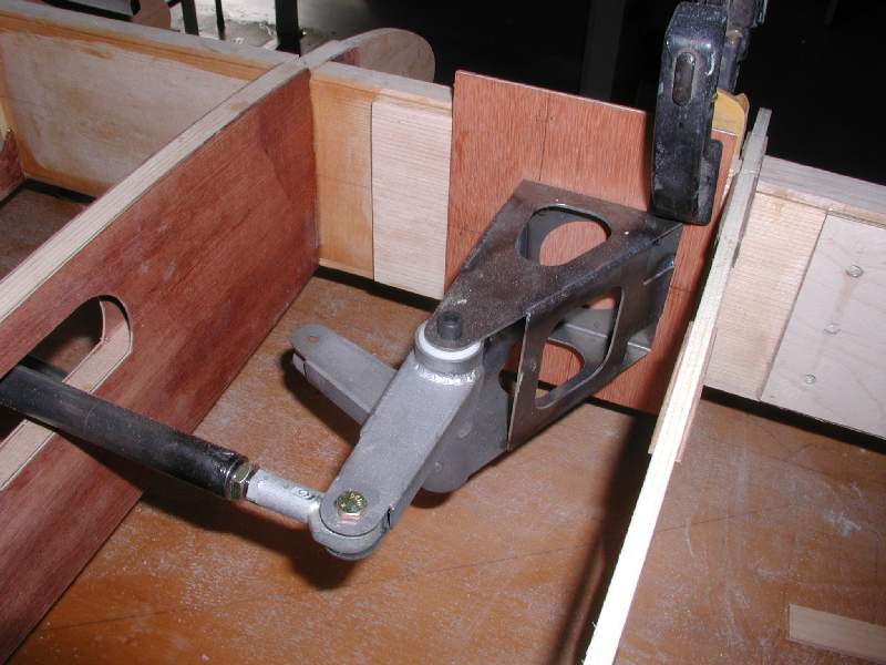
- The aileron bellcrank assembly has been temporarily put into place in the lower wing.
-
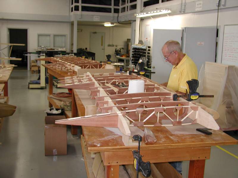
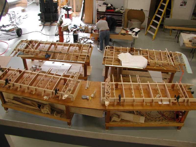
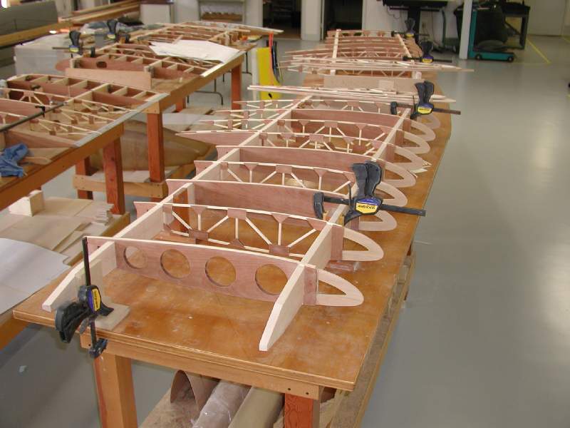
- A portion of our busy shop… while Barrett Brummet and Phil Everette work on the fuselage formers, John Hollister has been finishing up details on the lower wings and building the uppers.
-
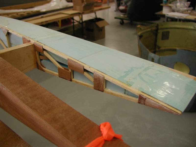
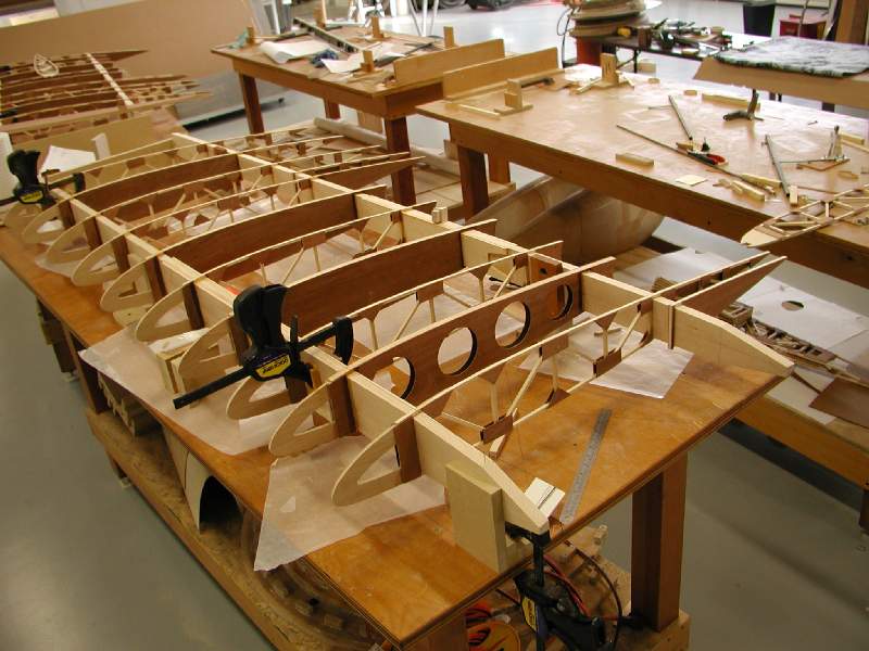
- The upper wing ribs have been placed onto the spars, but most have not yet been glued in place.
-
- The ends of the aileron bays have double ribs for stiffness, just like the lower wing. The space between the two ribs will be fully boxed with 1/16″ plywood.
-
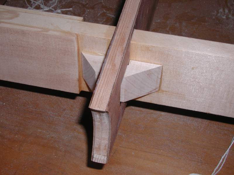
- This shows the hardwod blocks that the internal drag/anti-drag wires land on. The blocks and rib cutouts are being treaked slightly on production aircraft to allow for easier construction.
-
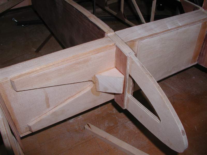
- Production kits will have modified nose ribs for use where there are wire blocks, in which the plywood will extend into the space between the wire mounting blocks. On the prototype, we inserted filler blocks to occupy this space… only a minor inconvenience.
-
- The ribs are being tacked into place with T-88. Later, they will be set on end and the ribs will be fillet-glued to the spars.
-
- John Hollister works on the upper right wing panel. The wings are well along.